

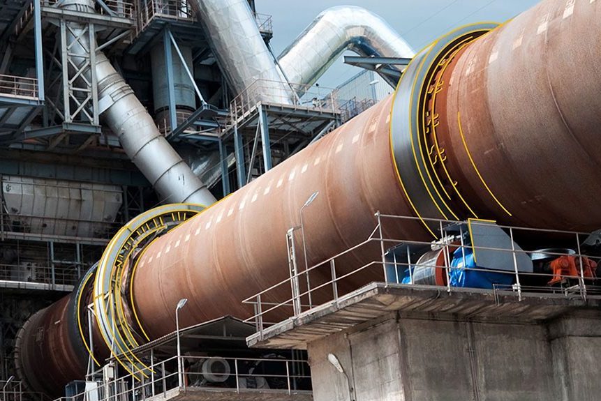

INSEE Vietnam selects its alternative-fuel injection points and calciner retrofit
Calciner of a 5,050 t/d clinker line · Problem: raising the alternative-fuel rate while holding CO and calcination · Tool: Simcenter STAR-CCM+
The right injection point for each alternative fuel
Retrofit decisions based on a model checked against plant measurements
Headroom for more alternative fuel and less fan power
INSEE Vietnam (Siam City Cement (Vietnam) Ltd), a member of the Siam City Cement group (Thailand), is one of the leading producers of cement and building mortar in southern Vietnam. Through INSEE Ecocycle, its Hon Chong plant has co-processed waste in the cement kiln since 2007 — more than 1.7 million tonnes of waste turned into recovered energy.
www.insee.com.vn ↗Raising the alternative-fuel rate while holding CO and calcination
INSEE wanted the calciner of its 5,050 t/d clinker line to take more alternative fuel. Besides 6 t/h of coal, the calciner already took rice husk, solid waste, discarded footwear and liquid waste — about 27.5 t/h, many pieces up to 80 mm. Fuel this coarse burns out only where it meets enough temperature and O₂ for long enough. Fed at the wrong point, CO rises, unburnt fuel falls back into the kiln and the raw meal calcines poorly.
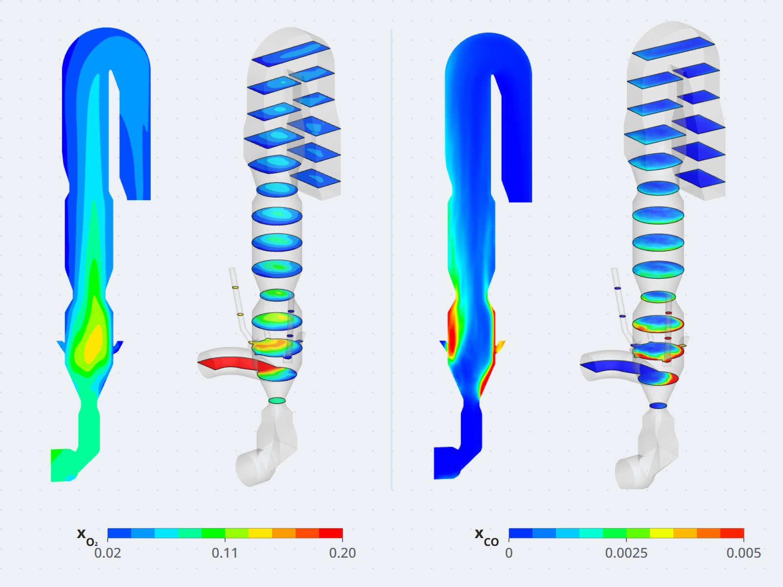
Measurements inside an operating calciner are not possible. The engineering team needed to know the gas flow, O₂ and CO in the vessel to select new positions for the feed chutes, and to assess each retrofit option before cutting into the equipment.
A virtual calciner calibrated to operation, three rounds of options with the plant team
CFDWAYS surveyed the site and confirmed the operating conditions with INSEE engineers (23–24 July 2025), then built a 3D model of the calciner in Simcenter STAR-CCM+, from the kiln outlet to just before cyclone C5. The multiphase model tracks the gas with coal, rice husk, solid waste, footwear, liquid waste and raw-meal particles, together with combustion and CaCO₃ calcination.
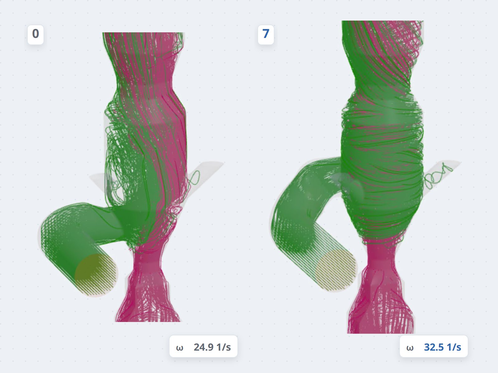
The model was checked against plant measurements, and every option was compared with the baseline on the same model. After each round — 6 flow options, 2 chute relocations, then option 7 — both teams reviewed the results and chose the next step. Option 7 brings the tertiary-air duct into the vessel tangentially, cyclone style, with the chutes rearranged at the same elevation, and was confirmed at a meeting at the plant.
A clear retrofit plan, with 3D drawings ready for implementation
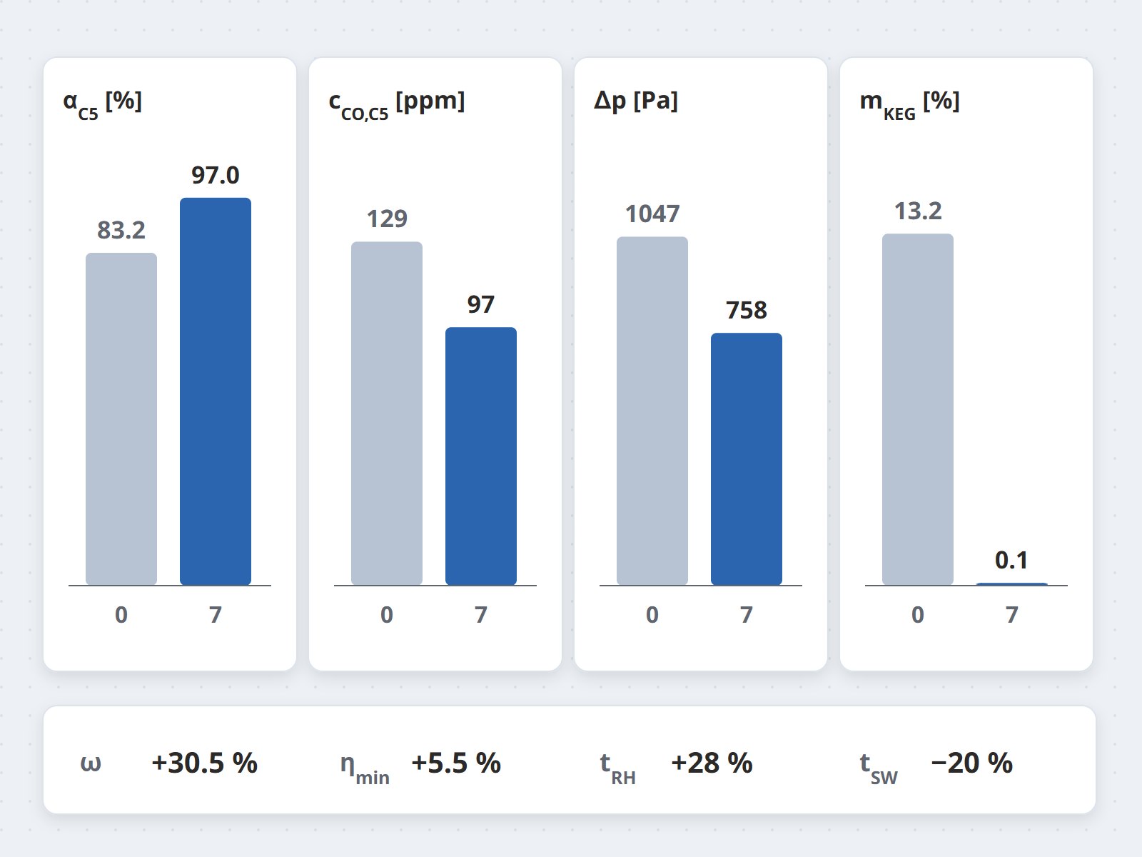
After 10 weeks, INSEE received the technical report and basic 3D drawings of the selected option. Against the baseline, option 7 delivers:
- Better burnout and calcination: calcination degree at the C5 inlet +16.6%, CO −24.9%, swirl in the vessel +30.5%.
- Almost no solids falling into the kiln: solids falling back into the kiln riser down from 13.2% to 0.1%.
- Pressure drop −27.6%: up to 32% less fan power for the calciner section, provided the ID fan stays at its best-efficiency point.
Lower CO at the same fuel input gives the plant headroom to raise the substitution rate while keeping CO at today's operating level.
Ask the CFDWAYS experts
Raising your alternative-fuel rate or retrofitting a calciner? Describe the line and its operating conditions — we reply within 24 working hours.