


Viglacera retrofits its spray dryers to cut wall build-up and dry more efficiently
Two spray dryers at a ceramic tile plant · Scope: hot-air duct and air distributor · Tool: Simcenter STAR-CCM+
The real cause of wall build-up and local burning identified
New designs verified before fabrication
Longer particle residence, lower pressure loss
Viglacera Corporation – JSC is one of Vietnam's leading building-materials producers, with product lines in glass, sanitary ware, ceramic and granite tiles, and fired clay bricks and roof tiles. Alongside building materials, Viglacera develops industrial parks and urban areas.
viglacera.vn ↗Dead zones caused local fires, and the hot gas pushed wet particles onto the wall
The plant runs two spray dryers. Dryer B uses coal-gasification gas at 520–550 °C; dryer C takes flue gas straight from a chain-grate furnace burning cashew shells and wood chips, at 670–690 °C. Together they turn about 28 tonnes of slip per hour into pressing powder.
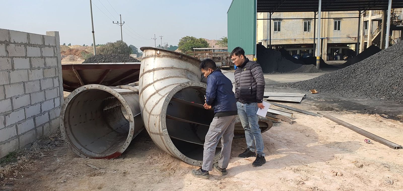
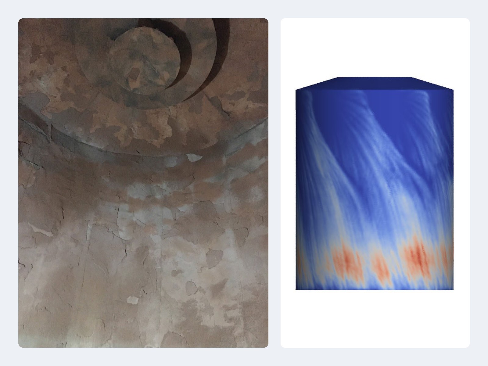
The hot-air duct and the air distributor had dead zones where coal dust and cashew oil collected, prone to catching fire and destroying the 304 steel parts. In the tower body, the hot gas swept still-wet particles onto the wall; slip built up and fell off in lumps of up to 20 cm, which can damage the exhaust duct and block the product outlet. The retrofit aimed to make the equipment last on alternative fuel, cut energy use, recover more product and reduce emissions.
Finding the cause by simulation, then a design for each dryer
CFDWAYS built a CFD model in Simcenter STAR-CCM+ of the hot-air duct, the air distributor and the tower body, based on the plant's operating data: hot-gas temperature, slip flow, and the direction and angle of the 12–20 spray nozzles. The model tracks the gas together with the drying slip particles and shows the dead zones, the high-velocity zones and where wet particles reach the wall.
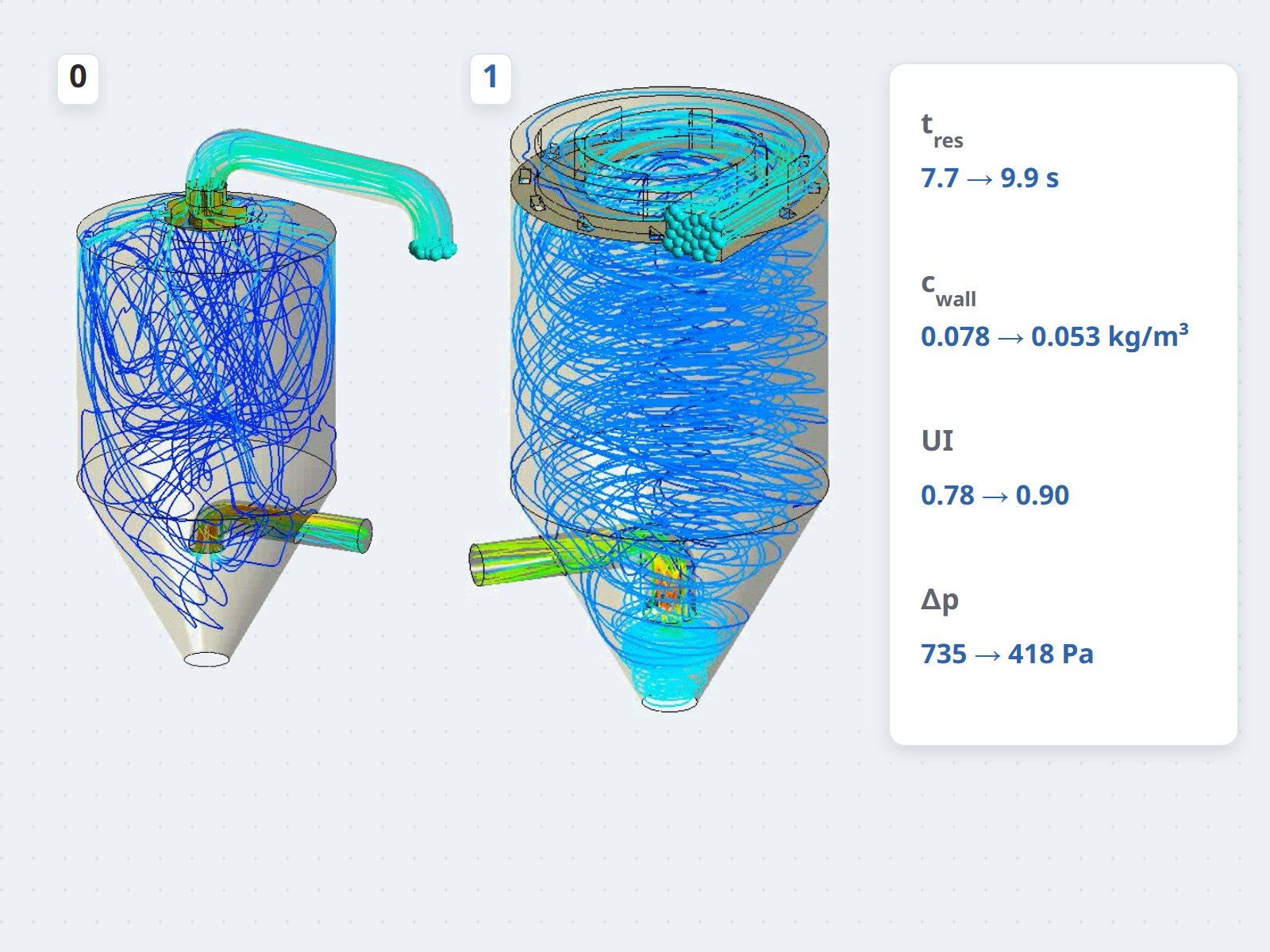
Each option was compared with the original design on the same criteria: pressure loss, local velocity, flow uniformity, residence time and particle concentration at the wall. Dryer B gained guide vanes before and after the hot-air duct bend. Dryer C moved to a cyclone-type air distributor: 4 main ports create a central swirl and 11 secondary ports with deflector hoods form a swirling gas layer along the wall. Both parts are built in heat-resistant 310S steel instead of 304.
Verified designs, fabricated and accepted against guaranteed values
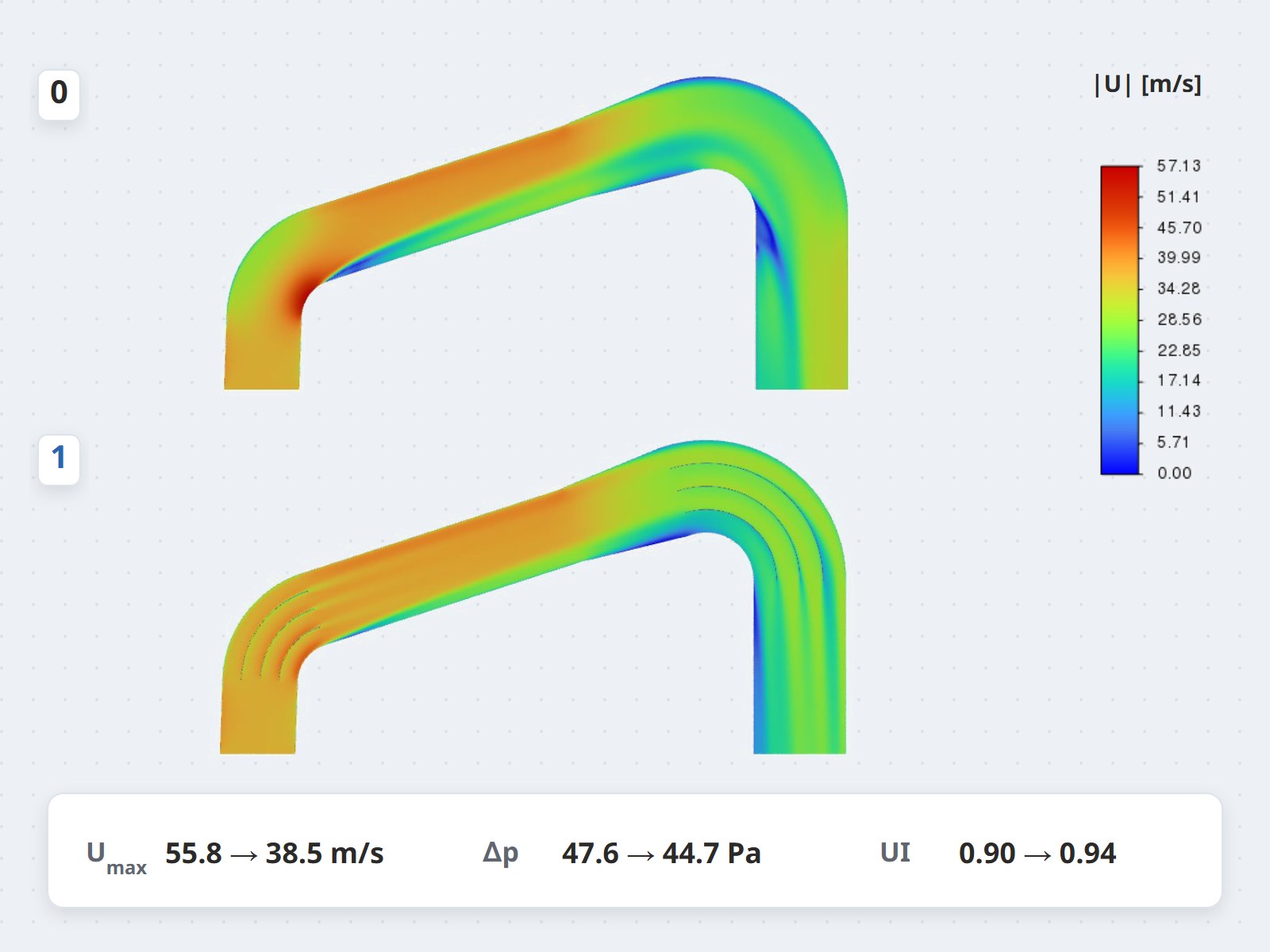
Against the original design, the simulation shows:
- Dryer C, cyclone-type air distributor: particle residence time 7.7 → 9.9 s (+28%), particle concentration at the wall −32%, hot-gas uniformity 0.78 → 0.90, pressure loss 735 → 418 Pa (−43%).
- Dryer B, hot-air duct with guide vanes: the reverse-flow pockets where coal dust collected are gone, peak local velocity 55.8 → 38.5 m/s (−31%), outlet uniformity 0.90 → 0.94.
- Values guaranteed at acceptance: residence time up more than 20%, wall build-up in the tower body down 20–30%; exhaust-duct pressure loss down 17%, cyclone train 620 → 490 Pa.
Longer residence dries the particles more evenly with the same hot-gas flow, giving headroom to cut heat consumption. The work received the Best Presentation award at the ICERE 2025 international conference.
Ask the CFDWAYS experts
Is your dryer building up on the wall, or are you about to change fuel? Send us the operating data — we reply within 24 working hours.